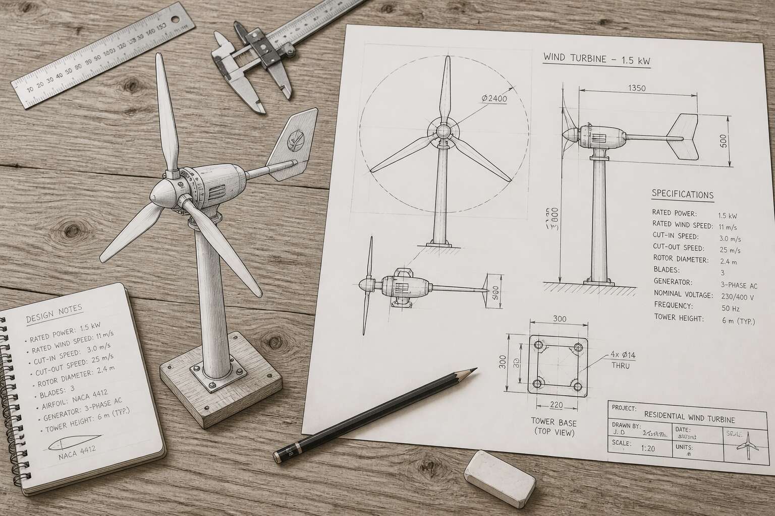
Understanding the Anatomy of Compact Wind Energy Systems
Rotor Blade Geometry and Pitch Angles
The rotor blade is where wind becomes work. In any small wind turbine drawing, the blade geometry and pitch angles determine whether that energy is captured cleanly or wasted. Chord width, twist distribution, and airfoil shape all matter. Pitch angle, the offset between the blade chord line and the rotor plane, controls how decisively the blade meets the wind.
Fixed-pitch blades are common in compact systems because they are dependable and inexpensive. Variable-pitch designs are heavier and more complex, yet they hold efficiency across gusty South African wind conditions. The relationship is direct:
– Wider chords generate more lift at low wind speeds
– Blade twist compensates for the changing velocity along the blade length
– Higher pitch angles reduce stall risk during strong gusts
Generator and Nacelle Internal Layout
They say the true heart of the machine is never seen. In a small wind turbine drawing, the nacelle is often rendered as a simple box, yet this unassuming housing conceals the quiet alchemy of generation. The permanent magnet alternator sits at the core, turning raw rotational force into useful current. The wiring looms and rectifiers perform their duties in close quarters, where heat dissipation becomes a primary concern.
The internal layout dictates the maintenance ritual. A well considered arrangement allows for essential servicing without unseating the entire unit.
– The yaw bearing enables true wind tracking
– A manual brake switch offers emergency stops
– The charge controller regulates battery voltage
Each component must be accessible, or the tower fatigue will outpace the wind.
Tower Designs – Monopole vs. Lattice Structures
The tower typically claims thirty percent of the project budget before one blade turns. That reality makes monopole versus lattice a question of logistics. In every small wind turbine drawing, the tower is the defining vertical element. Monopoles use a single tapered steel tube, resisting torsion well and offering a simple climbing path. Lattice towers use welded angle iron in a triangular or square truss, packing more surface area for the same height. More surface means more bolts and paint to maintain.
The structural tradeoff is straightforward, and it rarely gets the attention it deserves!
- Monopole towers flex less and suit automated winch-down maintenance.
- Lattice towers ship in modular bundles, which eases erection on rough terrain.
Neither option is universally superior. Wind shear and soil conditions push the final choice. A proper small wind turbine drawing must capture tower attachment points, foundation depth, and guy wire radius, if any.
Foundation and Mounting Considerations
In South Africa, a turbine foundation can consume a fifth of the entire budget before the tower arrives! That reality forces the mounting design to the front of every small wind turbine drawing. The base must resist overturning moments from high gust speeds, especially in the Cape winds.
Geotechnical surveys reveal soil bearing capacity, which varies sharply from clay to decomposed granite. Anchor bolt cages must remain aligned to the millimetre, because tower base flanges have zero tolerance for drift. I have seen a misalignment of a few millimetres force a complete remanufacture.
- Bolt tensioning sequence, which locks the flange evenly
- Grout levelness under the base plate
- Earthing conductor placement, which prevents lightning damage
Mounting style changes with terrain. A buried foundation suits level sites, while rock anchors and reinforced pads suit slopes. Every small wind turbine drawing should show these details.
Electrical Components – Inverters and Charge Controllers
Most small wind turbine drawing packages stop at the tower. That is a mistake. The inverter and charge controller decide whether your yield reaches the battery or vanishes as heat. I have watched systems lose a third of their output to a badly matched controller.
In South Africa’s variable wind regime, a charge controller must handle sharp voltage swings. The drawing needs to show its placement, cable gauges, and cooling airflow. A controller sealed in a box derates fast.
Consider these drawing musts:
- Inverter input range matched to the turbine’s peak voltage
- Charge controller setpoints for your specific battery chemistry
- AC and DC isolation points for maintenance
A dump load resistor belongs in the same schematic. Without it, overspeed on a gusty Cape day cooks the controller.
Essential Drafting Tools and Software for Technical Illustrations
Traditional Instruments – Compasses, Protractors, and Scales
Technical drawings for turbines begin with precision, not pixels. The journey of a small wind turbine drawing often starts with a sharpened pencil and a steady hand. Traditional instruments remain vital for establishing the foundational geometry that computer software later refines.
A compass, for instance, is indispensable for plotting the exact circumference of a rotor hub. Protractors allow you to mark blade pitch angles with accuracy, ensuring the aerodynamic profiles you sketched earlier translate correctly onto paper. A set of graduated scales enables you to represent a 10 meter tower height on an A3 sheet without distorting the proportional relationships between components.
These tools force you to consider each measurement deliberately. Before moving to a digital interface, many designers map out the complete assembly flow using only these instruments. This tactile process reduces conceptual errors and provides a physical reference for the electrical component placements you will detail next. The act of drawing by hand clarifies spatial logic in ways that a monitor cannot replicate.
Beginner-Friendly CAD Platforms (FreeCAD, Tinkercad)
The transition from paper to screen changes how we approach a small wind turbine drawing. While a pencil and compass establish the geometry, software unlocks the ability to test and manipulate every curve. The learning curve for professional programs can be steep, which is why starting with a simple configuration is wise.
For beginners, the choice of software matters less than the practice of using it. FreeCAD and Tinkercad offer distinct entry points. Tinkercad runs entirely in a browser, which means no installation hassles. It works well for basic layout and visualising the tower base. FreeCAD provides a parametric environment where you can adjust a single blade dimension and watch the entire model update. Both allow you to export files for further analysis.
– Use Tinkercad for rapid prototyping of your initial layout.
– Switch to FreeCAD when you need to manage tolerances for the mounting brackets.
A small wind turbine drawing requires precision, but these tools give you the freedom to iterate without redrawing from scratch. You can examine the junction between the nacelle and the tower with a clarity that static sketches cannot provide. The goal is to find a creative flow where you can actively refine your idea. The digital workspace is your workshop.
Professional Software Options – AutoCAD and SolidWorks
The leap from beginner-friendly tools to professional drafting software is significant, but the rewards are substantial when a project moves from the conceptual phase to fabrication. A small wind turbine drawing for a client in Johannesburg or a municipal project in Cape Town demands a level of precision that free, cloud-based tools often cannot deliver. The difference lies in the depth of control over every line, dimension, and material property. When you are designing for wind loads and fatigue, the accuracy of the model is directly tied to the safety and viability of the structure.
AutoCAD remains the industry standard for 2D schematics and detailed layout plans. It excels at producing the flat, scaled drawings necessary for manufacturing, such as the exact profile of the blade or the bolt-hole patterns on the hub flange. Its command-line interface is powerful, allowing for rapid adjustments to a small wind turbine drawing without disturbing the overall geometry. This level of control is essential when you need to check clearances or verify the precise angle of attack against local wind data.
SolidWorks, on the other hand, brings the third dimension into sharp focus. While a 2D drawing is perfect for a machinist, a 3D assembly is invaluable for the engineer. Here, you can virtually assemble the nacelle, the hub, and the blades to check for interferences that a flat schematic would miss. The simulation tools allow you to test how the rotor behaves under turbulent gust conditions, a common occurrence across the Highveld. You can adjust the airfoil thickness and observe the resulting stress distribution in real-time, a luxury that static paper sketches never afforded. This dynamic feedback loop is where a small wind turbine drawing transitions from an artistic exercise into a rigorous engineering document.
Using 3D Modeling for Exploded Views and Animations
A static drawing tells you what something looks like. An exploded view tells you how it fits together. For a small wind turbine drawing, that distinction matters when you are explaining the relationship between the rotor hub, the brake disc, and the generator shaft to a client in Durban or a workshop in Polokwane. Animations add another layer, showing the sequence of assembly or the flow of air over the blades in motion.
I have found that a few tools handle this kind of technical illustration particularly well:
– Blender for free, open source animation and exploded view rendering
– Fusion 360 for parametric modeling with integrated motion studies
– KeyShot for fast, photorealistic visuals without a steep learning curve
Each of these lets you rotate a small wind turbine drawing in real time, exposing interferences that a flat schematic would hide. The result is a document that speaks clearly to both the engineer and the investor.
Vector Graphics vs. Raster – When to Use Each Format
The humble vector file might be the most underappreciated element in any technical drawing workflow. When I am working on a small wind turbine drawing, the choice between vector and raster is the first decision that shapes everything that follows. Raster images are made of pixels, and they behave like wet clay; you can push them around, but they will eventually show their limits. Vectors, by contrast, use mathematical formulas to define lines, meeting the needs of precision work.
For components like the blade tip or tower base flange, a raster file loses its crispness the moment you zoom in too far. Vectors hold their edge. Here is the simple breakdown I use with junior drafters:
– Vector for line work and scaling; it never loses quality
– Raster for photorealistic textures; think site backgrounds or material simulations
Yet, raster has its place. If you are overlaying wind speed heat maps onto a photographic site survey, a raster is your ally. The resolution is fixed, but the context it provides is unmatched.
The pipeline works best when you can switch between them. I always export the final small wind turbine drawing as a vector for the workshop, while sending a high resolution raster to the client for their presentation. One file is for cutting steel, the other for painting a picture.
Step-by-Step Process for Creating a Schematic Blueprint
Setting Up the Drawing Scale and Boundary
In the Karoo, a misplaced line on a small wind turbine drawing means wasted steel and a long walk back to the workshop. The first step in creating a schematic blueprint is setting the drawing scale and boundary. This decision controls every measurement that follows.
Measure the rotor diameter first. Then pick a scale that fits within the paper, such as 1:50 for a full assembly. Draw the boundary as a rectangle with a consistent offset from the edge, usually 10 mm. The boundary keeps the drawing inside the printable area.
- Confirm the largest component dimension.
- Choose a common metric scale.
- Set the boundary before adding any detail.
Drafting the Tower Base and Vertical Axis
The open plains of the Karoo teach a harsh lesson in preparation. A single misaligned mounting hole on a small wind turbine drawing translates into a day lost on site, wrestling with steel under a merciless sun. Precision is not pedantry; it is the only thing standing between a successful installation and a costly reboot.
This is where your initial drafting discipline pays for itself. When you begin your small wind turbine drawing, the scale you chose earlier now dictates every geometric truth. A tower base plate drawn at the wrong nominal size becomes a wobbling anomaly, while an incorrectly dimensioned vertical axis creates a turbine that screams in the wind. You are not just sketching lines; you are defining the machine’s structural integrity.
The Foundation of Form
Start with the tower base, the anchor of your entire structure. Draw the base plate in plan view first, establishing the bolt circle for the anchor bolts with absolute certainty. Here, the symmetry is critical, but the real subtlety lies in the transition. From the base plate, extend the vertical axis upward. You must show the wall thickness of the tower and the weld details, not merely the outer silhouette. This isn’t about aesthetics; it is about the load path.
Once the vertical axis is established, shift to the nacelle interface. The hub height is a calculated figure, not a guess. Your small wind turbine drawing must bridge the static tower with the dynamic rotating assembly. Pay close attention to the tolerances between the low-speed shaft and the bearing housing. A few tenths of a millimetre here can mean the difference between a smooth rotation and a catastrophic seizure.
Capturing the Assembly
As you move through the drafting process, remember that you are creating a roadmap for fabrication. Do not hide the complexity. Where the brake disc mounts to the shaft, provide a detailed callout. Where the yaw bearing sits, show the clearance required for the power cable twisting. For a professional output, you will need to specify:
– The exact thread pitch for all fasteners.
– The surface finish on the mating flanges.
– The specific welding standard for critical joints.
– The directional orientation of the blade root flanges.
By ensuring each of these elements is clearly annotated within your small wind turbine drawing, you eliminate the need for verbal guesswork on the workshop floor. The drawing becomes the single source of truth, allowing a fabricator in Johannesburg to build a component that fits perfectly with one made in Cape Town. That level of clarity is what transforms a simple sketch into a professional specification.
Sketching the Nacelle Housing and Hub Assembly
When you begin a small wind turbine drawing for the nacelle, resist the urge to sketch the housing first. The housing is a metal raincoat. The hub assembly is the skeleton. Mark the shaft centreline, then locate the blade root flanges around it. Every pitch bearing needs a coordinate, not an estimate.
- Position the hub centre and draw the blade root bolt circles.
- Add the low-speed shaft with bearing seats and stated tolerances.
- Outline the housing walls with clearance for the yaw drive and cable loop.
- Annotate brake calliper mounts and the anemometer bracket.
That sequence keeps the small wind turbine drawing honest. A fabricator near Upington can follow it without a phone call. The housing shape is the final stroke, since it only needs to fit what is already placed inside.
Detailing Blade Profiles and Aerodynamic Curves
A schematic blueprint for a rotor blade is an exercise in controlled extremes. You are not just drawing a shape; you are recording a specific twist of air and force. Start by laying down the chord line. This is your anchor. From here, you define the pressure side and the suction side as distinct mathematical functions, not just pretty curves.
The leading-edge radius requires a separate, detailed callout. The trailing edge often vanishes into a hairline, yet it bears the entire load of the design. Use a series of overlapping splines to trace the transition from root to tip.
- Define the coordinate system.
- Plot the camber line.
- Distribute surface points.
The result is a small wind turbine drawing that speaks in coordinates, not guesses.
Adding Dimension Lines, Tolerances, and Annotations
A 0.5 millimetre error on a blade root shifts the performance curve of a small wind turbine drawing into an entirely different machine. I start with dimension lines. Define a single datum reference. Every measurement flows from that fixed point, never from the nearest edge. Chain dimensioning invites cumulative error. Baseline dimensioning keeps each coordinate independent. In a country like South Africa, where wind loads vary dramatically from coast to interior, this discipline matters more than aesthetics.
- Indicate feature control frames for critical bore holes.
- Apply geometric tolerances in addition to linear ones.
- Call out surface roughness for bearing seats.
Annotations supply intent. Without them, a drawing is a collection of shapes. With them, each coordinate defines a limit. The tolerance value is a boundary condition. These boundaries decide whether a rotor survives its first summer storm. Every reliable small wind turbine drawing communicates this way, translating engineering judgment into measurable constraints.
Including Wiring Diagrams and Connection Points
Every small wind turbine drawing depends on the electrical schematic for its full meaning. Start by tracing the power path from the alternator terminals down through the tower. Mark each junction where a cable meets a component. Use numbered tags that match the mechanical drawing’s datum references.
A schematic blueprint maps physical locations. For a South African installation, this matters when lightning protection routes must follow the shortest path to earth. Define each connection point with a label that refers back to the coordinate grid.
The process follows a strict order:
– Identify the alternator output terminals and assign unique identifiers.
– Plot the rectifier and controller positions relative to the nacelle layout.
– Draw the cable routes with bend radii that match real tower dimensions.
– Mark every ground point with a distinct symbol.
This sequence keeps the small wind turbine drawing coherent between disciplines. Each connection point must correspond to a measurable position.
Comparing 2D Orthographic Projections with 3D Isometric Views
Front, Side, and Top Elevations – Why They Matter
A 2D orthographic projection gives you the exact truth of dimensions. It isolates the front, side, and top elevations, stripping away perspective distortion for precise measurement. A 3D isometric view provides a clear, single-image grasp of the overall assembly.
When creating a small wind turbine drawing, I use 2D views to verify structural offsets. The 3D is better for visualizing the component relationships. That said, the 2D top view is where you really see the layout of the blades. The 3D is where you see the physical shape.
Isometric Sketching for Visual Clarity
When I compare 2D orthographic projections with 3D isometric views, I often say the former is for engineers who like certainty, while the latter is for humans who like to see what they are building. The 2D view delivers exact dimensions, but the 3D view clarifies how the hub meets the blade. Isometric sketching for visual clarity is a practical tool. It lets you examine a small wind turbine drawing from every angle without changing your physical position.
Here is what works for me when choosing between the two:
- Use 2D for verifying offsets and tolerances.
- Use 3D for explaining the assembly to a colleague.
- Use both when the client asks, “But what does it actually look like?”
The 3D isometric view does not offer the same measurement precision, but it excels at showing how the nacelle sits atop the tower. For a small wind turbine drawing, that visual clarity often saves more time than a dozen dimension lines.
Cutaway Views to Reveal Internal Gearing
A cutaway view is the closest thing to x-ray vision that a draughtsperson can offer. While a 2D orthographic projection gives you exact dimensions, it does not tell you how the planetary gears mesh with the main shaft. That is where the cutaway earns its keep.
The 3D isometric view helps a colleague understand the nacelle shape, but the cutaway reveals what the casing hides. You see the gearbox, the brake disc, and the generator rotor in one clean sequence.
When I prepare a small wind turbine drawing for a client in Johannesburg, I provide 2D sheets for the workshop, an isometric for the site meeting, and a cutaway for the investor who wants to see where the torque flows. Any decent small wind turbine drawing set includes all three.
My rule of thumb:
- Use orthographic views when dimensions decide the argument.
- Use isometric views when assembly order matters.
- Use cutaway views when someone asks, ‘but what turns inside?’
Exploded Diagrams for Assembly Instructions
Every drafting assignment presents a singular challenge: which visual language will communicate the design fastest? In my workshop, I often field this question from clients balancing tight deadlines and tighter budgets. The answer rarely lives in a single style. A professional set of small wind turbine drawing documentation should be a deliberate mix of precision and perception, a narrative built for different readers.
The 2D orthographic projection is my preferred tool for matters of strict measurement. When a specific clearance, say a 5 mm gap between the hub and the spinner, makes or breaks the design, I rely on 2D. It is uncompromising and exacting. Conversely, the 3D isometric view is about spatial reasoning. It shows how the nacelle sits atop the tower. Yet, neither truly captures the process of assembly. That is the domain of the exploded diagram, which uses 3D space to tell a story.
Where the 3D isometric shows what fits together, the exploded diagram shows how. This is a crucial distinction. I once watched a team struggle with a gearbox installation because they skipped the exploded view. They had the dimensions, but they could not visualise the order of operations.
Here is the order of operations I insist upon for clarity:
- Start with the main shaft as your anchor point in the layout.
- Draw the components floating directly above their final resting place.
- Use a consistent gap between each part to suggest the sequence.
This method ensures that even a complex small wind turbine drawing with multiple components remains readable. It is the difference between handing someone a map and walking them through the route. A good set of drawings accounts for the tools, the technician, and the inevitable questions that arise when theory meets the tower site.
Photorealistic Rendering for Stakeholder Presentations
In a Sandton boardroom, a 2D orthographic projection can stall a discussion! The coordinates are exact, but they do not convey the physical presence of a device on the site. A small wind turbine drawing must carry two audiences, the engineer and the funder.
The 3D isometric view provides the spatial relationship between the orientation, hub, and tower. Photorealistic rendering adds a tactile quality. It shows a texture, the grazing of light, and the metallic form against the Karoo horizon. This is a strong visual tool.
For stakeholder presentations, I compare these three visual ranges. The 2D sheet holds the measurement. The isometric view explains the orientation. The photorealistic articulates the environment. In a small wind turbine drawing, each has a specific role
.
- The 2D orthographic projection for the fabrication,
- The 3D isometric for the assembly sequence,
- The photorealistic rendering for the site approval.
Common Pitfalls in Drawings and How to Avoid Them
Incorrect Blade Twist and Chord Distribution
Blade twist and chord distribution are where small wind turbine drawing efforts go sideways. A blade that looks elegant on screen fails in reality because the twist angle stays constant instead of decreasing toward the tip. Such a rotor produces less power than a ceiling fan during load shedding.
Chord distribution is equally abused. Some drafts use a uniform chord width, which is easier to draw but aerodynamically lazy. The blade should taper, with the widest section near the hub. Without this, the turbine stalls and vibrates like a disgruntled kettle.
Common offenders include:
- Copying a blade profile from a larger turbine and scaling it down, ignoring Reynolds number effects.
- Ignoring the twist axis location, so the pitch mechanism jams.
- Treating the chord line as decorative, leading to excessive flex.
Every small wind turbine drawing should show twist values at multiple stations along the blade. Mark them. Your future self will thank you.
Neglecting Tower Base Stress and Wind Load Calculations
The draw of a sleek tower is seductive, but the numbers beneath it hold the true story. Too often, a small wind turbine drawing treats the foundation as an afterthought, a simple pad of concrete drawn as a rectangle. This is where the quiet, grinding failure begins. The soil conditions in the Free State or the wind regimes of the Capes demand a specific, calculated base. A drawing without the soil bearing capacity or the calculated bolt sizes for the tower flange is just a picture, not a blueprint.
Wind loads create a bending moment at the base that will eventually exceed the yield strength of the steel if the draft is ignored. One concise drawing should show the reaction forces and the shear diagram. A substandard addition to this is the cable and anchor points, which are often incorrectly placed. Static tension is fine, but the fatigue from vibration is the killer.
A proper specification must enforce these parameters:
1. The foundation depth and rebar schedule.
2. The anchor bolt radius and embedment.
3. The base interface plate thickness and weld profiles.
Without this data, the mast is a lever waiting to snap. The fatigue from vibration is a raving force. Specifying the correct base capacity morphs the art of drafting into an engineering practice. That leap is what separates a sketch from a functional small wind turbine drawing.
Overcomplicating Wire Routing Paths
A cluster of tangled lines on a small wind turbine drawing does not impress an installer. It confuses them. Wire routing paths are often overcomplicated because the drafter tries to show every cable, every bend, and every junction in a single view. This creates a mess that fails in the workshop and on the mast.
A proper small wind turbine drawing separates cable runs by function and voltage. It respects ampacity limits and shows clear entry and exit points at the nacelle, the tower base, and the control board. The route follows the shortest safe path, not the path that looks technically impressive.
What should appear on the sheet:
- The physical path each conduit takes through the tower.
- The separation distance between power and signal cables.
- The slack allowance at every connection point.
A clean routing plan is a sign of a drafter who has actually built something. I trust a drawing that shows restraint. Clutter disappears when every line has a purpose.
Missing Safety Features – Fuses and Emergency Brakes
A small wind turbine drawing that omits fuses or an emergency brake is a liability on paper and on the mast. I have seen designs that look elegant yet fail the first safety review. The rotor spins, the inverter hums, but nothing isolates a fault or stops the blades in a storm.
Safety features are not decorative additions. They are the difference between a survivable failure and a catastrophic one. A proper drawing must show:
- The fuse rating and location for every DC and AC circuit.
- The emergency brake actuator and its control path.
- A manual disconnect that a technician can reach without climbing.
Without these, the small wind turbine drawing is incomplete. Installers in South Africa face high wind events, and a brake that cannot be triggered remotely is a danger. The drawing must reflect that reality!
Inaccurate Scaling Between Components
Scale errors hide in plain sight. A small wind turbine drawing with mismatched proportions looks plausible at a glance, yet fails when parts arrive on site. The rotor hub dwarfs the nacelle, or the generator appears smaller than its controller. These inaccuracies confuse the workshop and the installer.
Avoid this pitfall by setting a reference dimension before drawing. Use the tower flange diameter as the fixed measure. Every component must relate to it numerically, not visually. In South Africa, where fabrication often happens far from the design office, precise proportions in the drawing prevent costly rework and wasted material orders.
Skipping Revision History and Version Control
A small wind turbine drawing without version control carries hidden risks. The workshop fabricates from revision two, while the installer reads revision four. A flange changes size, a bolt pattern shifts, and steel arrives pre-drilled for a drawing that no longer exists.
In South Africa, projects cross time zones and site offices. A drawing gains annotations from three different engineers. Without a revision history, no one knows which markup is current. The design office approves the latest file. The workshop disagrees. The discrepancy surfaces when components fail to align.
Set a simple rule: every change gets a revision letter, a date, and a note.
- Track the revision letter on every issued drawing.
- Record the change date and the author.
- Archive superseded versions separately.
This costs minutes per edit.
Optimizing Your Blueprint Content for Search Engines
Targeting Long-Tail Queries Like ‘How to Draw a Micro Wind Spinner’
When someone types “how to draw a micro wind spinner” into a search bar, they are often standing in a shed with a ruler and a pencil. They want a small wind turbine drawing they can actually build. Your blueprint content needs to meet that practical need.
The best search optimisation happens when you mirror the language people use in real life. That means including phrases like blade chord, hub offset, and tower bolt pattern. A South African builder working with 2 metre rotor diameters faces different wind conditions than someone in Europe. The small wind turbine drawing should reflect those regional realities.
- They look for free resources before paying for software.
- They compare hand drafting with CAD outputs.
- They search for specific measurements, not general theory.
Targeting long-tail queries requires patience. The traffic is smaller, but the people arriving are ready to draw!
Using Image Alt Text and Descriptive File Names
An image labelled ‘IMG_2045.jpg’ gives search engines no information. A file named ‘2m-rotor-lattice-tower-plan-view.png’ gives clear context. When you upload a small wind turbine drawing, the filename and alt text carry the descriptive load. Use filenames that include rotor diameter, tower type, and view. Describe the image in alt text as you would to a colleague. ‘Brownfield hub assembly with blade pitch angles’ is more useful than ‘diagram’.
Search engines cannot see the drawing. They rely on surrounding text. A descriptive filename functions as a caption, and alt text functions as a transcript. For a drawing of a micro wind spinner, include ‘small wind turbine drawing’ in the alt text once. Add specific measurements to the filename:
- Include scale and units, for example ‘scale-1-10-metres’.
- Mention the component, such as ‘hub-offset-section’.
This practice improves indexing without confusing human readers. A blueprint named ‘scan0012’ invites obscurity.
Embedding Downloadable PDF and CAD Templates
Almost every visual asset we create for renewable energy projects gets buried in a folder, named something like “Final_v3.” There is a quiet tragedy in that. When you offer a downloadable PDF or CAD file, you are not just providing a file. You are providing a narrative. The search engine needs that narrative to be explicit. A file named `10kW_ac_export.dwg` is a cipher. A file named `small wind turbine drawing, 5kW, lattice tower, foundation detail` is a map. The difference is the effort you put into the metadata, which is the only language an indexer understands.
Treat your downloadable assets as an extension of the page itself. If you have a CAD template for a tower hub, state that the file contains the reference dimensions. The anchor text for the download link should be a sentence, not a label. “Download the scaled hub assembly for a 2m rotor” tells the user and the crawler what they will get.
Consider the internal structure of the file.
– Include a dedicated layer for all dimensions.
– Name that layer “Scale_Annotations.”
– Place the title block with the projection method and the date.
– Embed the coordinate system for the GIS data.
This makes the file professional for the engineer who downloads it. It also gives you a reason to use those descriptive terms in your article, which bolsters the relevance for a small wind turbine drawing query.
The act of naming is an act of curation. Remember the earlier advice about the alt text? The idea is the same. A drawing reduced to an image tag is just decoration. A drawing described as “generator nacelle cutaway with brake mechanism” becomes part of the textual fabric of your site, a thread that leads a reader from a problem to a solution. That is the real point of optimizing the blueprint content. It is not about tricking a machine. It is about making the information of your design work visible to anyone who asks the right question.
Linking to Related Tutorials on Renewable Energy
The single most powerful asset in your renewable energy project might not be the turbine itself, but the drawing that defines it. A well-executed small wind turbine drawing tells a story of efficiency, foresight, and engineering discipline. It serves as the definitive communication tool between the designer, the fabricator, and the installer. While we often focus on the physical assembly, the blueprint is where the true problem-solving occurs. It forces you to reconcile the theoretical output with the physical constraints of your materials and your chosen site.
A successful drafting session is rarely about the aesthetic representation; it is about the decision-making process that happens before the pencil hits the paper. You must interrogate your own design. Will the chosen alternator fit within the nacelle envelope? Is the yaw bearing oversized enough to handle the thrust loads at your maximum wind speed? These are questions that a preliminary sketch will expose long before you commit to expensive steel. This phase of preparation saves time, money, and considerable frustration during the actual build.
When you move to the final technical illustration, remember that you are creating a manufacturing specification, not just a visual aid. For instance, when you plot the topology of the electrical system, you are mapping the flow of energy. Similarly, when you dimension the tower base flange, you are implicitly calculating the bolt shear stress. Consider the necessary layers of detail that add value to the end user.
– Identify all hardware, specifically grade markings for bolts and fasteners.
– Specify weld types, whether fillet or butt, rather than leaving it to assumption.
– Call out the surface finish for the blade roots to ensure a proper mechanical fit.
These details seem minor, but they distinguish a hobbyist sketch from a professional document. The goal is to eliminate ambiguity so that a third-party fabricator can produce your components without requiring a phone call to clarify your intent. The clarity of your dimensions directly impacts the precision of the final machined part, especially when dealing with the critical airfoil profile on the blades.
Ultimately, a small wind turbine drawing is the translation of a complex mechanical concept into a universal language. It bridges the gap between the raw physics of the wind and the tangible reality of a spinning rotor. By treating your drawings with respect and rigor, you elevate the entire project. You create a permanent record that can be refined, revised, and improved upon in future iterations, ensuring that your next turbine is always better than your last. That is the true legacy of a thoughtful engineer.
Encouraging User Comments and Q&A Integration
When you publish a small wind turbine drawing online, the text around it determines whether South African makers find it. Search engines crawl the alt text, file names, and surrounding paragraphs. I always remind readers that a drawing of a 3-meter rotor with a permanent magnet alternator needs descriptive context, not a JPG named “turbine-final-v2.”
User comments and Q&A sections turn a static blueprint into a living document. Someone in Cape Town might ask about flange thickness for a 12-meter tower. Another user in Johannesburg might share how they sourced the bearings locally. These exchanges add unique text that search engines index. Over time, that small wind turbine drawing becomes a hub of shared knowledge. That is the kind of content I love to see.




0 Comments