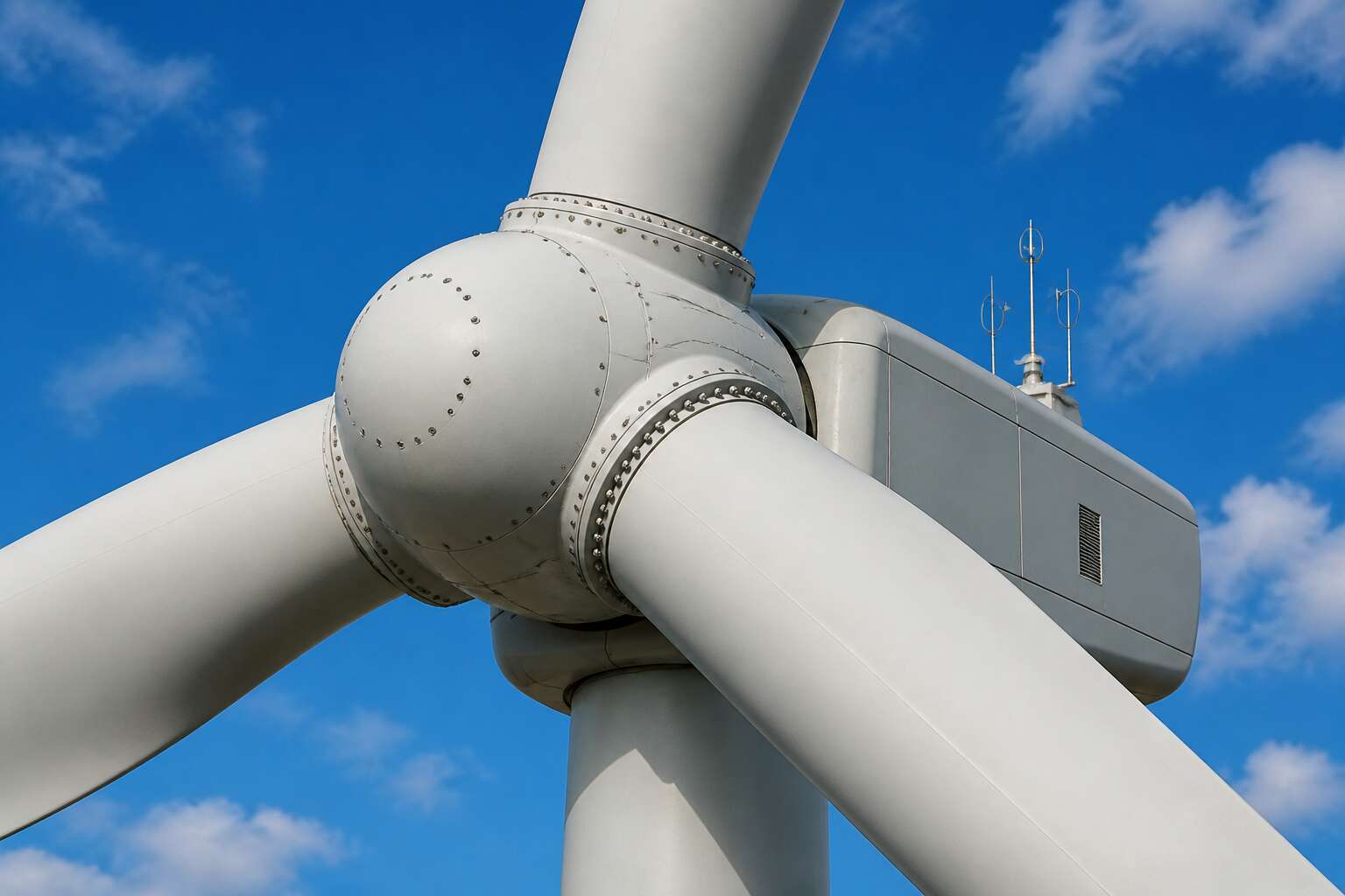
Anatomy of a Wind Turbine Rotor Assembly
The Central Hub and Its Role
The central hub is where the blades in wind turbine are connected to, a steel node that endures forces most structures never face. It holds the rotor together while transmitting torque to the drivetrain. Without this component, the entire assembly would shear apart under its own weight.
The hub does more than anchor. It allows pitch control, letting each blade adjust its angle to the wind. This is where mechanical engineering meets survival instinct, a constant negotiation with nature’s unpredictability.
- It transfers aerodynamic loads to the main shaft
- It houses the pitch bearings and controls
- It protects critical mechanisms from exposure
Understanding the hub means understanding how a turbine stays upright when storms hit. This component must flex without failing, a balance between rigidity and resilience that defines the whole machine.
Blade Root Geometry and Interface
The blade root is a thick circular flange that tapers into the aerofoil shape. The blades in wind turbine are connected to the hub through this interface, which relies on dozens of high-tension studs. Each stud carries shear and bending loads from the rotor.
The geometry transitions from a rigid circle to a flexible shell. This transition zone is where cracks often initiate if the design fails to distribute stress evenly. The interface also houses a pitch bearing, allowing the blade to rotate around its longitudinal axis.
- A bolt circle machined to exact tolerances
- A tapered transition that blends flange and shell
- Dedicated channels for lightning discharge
South African wind farms face unique erosion and thermal cycling, so the blade root interface must accommodate these conditions without compromising the seal against moisture and dust.
Pitch Bearings as the Connecting Link
A wind turbine rotor is a study in controlled tension. The hub may anchor the assembly, but it is the pitch bearing that determines how the blades in wind turbine are connected to the broader system of energy capture and structural survival. This bearing is a massive ring of precision steel, often exceeding three meters in diameter, designed to manage the immense cantilevered weight of a spinning rotor blade. It must hold the blade rigidly during a gale, yet allow a fractional rotation to feather the aerofoil for optimal load management.
Every pitch bearing is a composite structure, using a mix of castings and forgings. It permits the blade to rotate around its longitudinal axis while transmitting the full spectrum of mechanical loads from the blade root into the hub. The bearing’s raceways are hardened to withstand the repeated micro-movements known as fretting.
The demands placed on these components are extreme; it is a constant fight against creep and fatigue.
Design standards for these bearings often follow rigorous certification regimes. The selection of a specific bearing configuration, be it a single row four-point contact ball bearing or a double row tapered roller bearing, depends on the turbine’s rotor diameter and the site’s specific wind class. Larger turbines tend to favor the latter for their higher load-carrying capacity.
Nose Cone and Spinner Attachment
The nose cone is the aerodynamic counterweight to the mechanical drama behind it. It deflects the wind’s first assault, shielding the vulnerable intersection where the blades in wind turbine are connected to the hub’s forward flange. Without this shell, the assembly would suffer from parasitic drag and increased turbulence at the root, which directly impacts energy yield. The spinner is not merely a cap; its curvature is designed to shed moisture and debris, keeping the surface clean for optimal airflow. Internally, the cone housing provides a dry corridor for the pitch system’s control lines, a protected space for technicians during maintenance.
Manufacturing these spinners often involves a vacuum infusion process for the composite halves, then a precision bolted joint to the hub. This method creates a rigid shell that resists vibration. The attachment hardware is typically access hidden by a removable tip, a thoughtful detail for service efficiency. The weight is a constant consideration. A lighter spinner reduces the rotor’s moment of inertia, which is critical for responsive yaw control. Modern spinners also integrate discrete grounding paths to dissipate lightning strikes safely to the hub, protecting the expensive pitch bearings downstream.
These components are classified by their ability to withstand enormous static pressure differentials. The surface area is vast, so even small wind gusts create significant loading on the panel fixings. Therefore, the design standard dictates a specific torque for each bolt. Additionally, the sealant between the spinner halves must remain elastic for decades, resisting UV degradation and thermal cycling. This seemingly passive part is a masterclass in applied composite engineering, ensuring the primary power generation, the blades themselves, face the elements with an unblemished leading edge.
Mechanical Connections and Fastening Methods
Bolted Flange Connections at the Blade Root
One less obvious truth is that the wind farm technician’s true adversary is not the gale, but the relentless vibration that seeks to loosen every single component. At the blade root, this battle is fought with a ring of high-tensile steel bolts that clamp the blade’s flange to the pitch bearing. This bolted connection is the physical manifestation of a promise that failure is not an option. The structural integrity of the entire turbine depends on the preload, the initial tension applied to each fastener, which must be precise. Without this calculated clamp force, the sheer forces from the wind will fatigue the steel far faster than any predictive model can forecast.
The interface itself is a study in engineered precision. A machined steel flange at the root provides a perfectly flat surface, mated against the bearing race. It is a connection designed for the millimetre, because even microscopic gaps invite microscopic movement, which leads to fretting wear. Hydraulic tensioners are used to stretch the bolts to a specific elongation, rather than relying on torque, to ensure every fastener shares the load equally. This is how the blades in wind turbine are connected to the main assembly with such unerring confidence. The maintenance crew will often find that the bolts require a re-tensioning pass after the first few months of operation, a settling-in period for the steel and the composite materials.
> – Sequential tightening patterns to ensure even load distribution
> – Ultrasonic analysis to measure bolt stretch, not just rotational tension
> – Surface coatings to prevent galvanic corrosion between steel and carbon fibre
The flange design must also account for the massive overturning moments generated during a sudden yaw or a wind shear event. The connection cannot be a rigid weld; it must be a semi-flexible joint that allows for slight bending without plastic deformation. This bolted arrangement provides that specific resilience, enabling the blades to shed turbulent energy without transferring catastrophic stress directly to the drivetrain. The bolts are the sacrificial guardians, absorbing the cyclical loads so the more expensive components behind them remain safe.
Stud Bolts and T-Nut Systems
Somewhere in the quiet hum of a turning rotor, the fastening methods become the quiet guardians of the entire assembly. For many tower designs, the answer to how the blades in wind turbine are connected to the pitch system lies in the use of stud bolts. These are not simple screws. They are long, fully threaded rods that are embedded into the blade root or passed through the flange. On the opposite side, a T-nut system grips from within, creating a robust clamp that resists the constant tug of aerodynamic forces.
Stud bolts offer a distinct advantage during maintenance. A technician can replace a damaged fastener without dismantling the entire blade assembly. The T-nut provides a secure anchor point that distributes the clamp load over a wider surface area of the composite material. This is critical because the blade root is not infinitely stiff. Too much pressure in one spot can cause localised crushing, so the load spreading is a practical necessity.
– Thread profiles are selected to resist vibrational loosening
– T-nut bases are often serrated to bite into the laminate surface
– Locking compounds are applied to the threads to prevent migration
The installation sequence relies on a specific pattern that pulls the joint together evenly. A technician will torque the bolts in a star or cross pattern rather than working around the circle. This prevents the flange from warping and ensures that the blades in wind turbine are connected to the bearing with a consistent preload. The real challenge comes from the material mismatch. Steel bolts expand and contract at a different rate than the composite blade root, so the fasteners must be able to flex without losing their grip over the turbine’s lifespan.
Hydraulic Tensioning for Uniform Clamping
Hydraulic tensioning offers a different path than torque wrenches. A hydraulic tool pulls the stud axially to a precise elongation, stretching it along its length. The nut is then run down against the flange while the tension is held. When pressure releases, the bolt contracts and clamps the joint with a predictability that torque alone cannot match.
This matters because the blades in wind turbine are connected to the pitch bearing through a joint that must survive decades of cyclic loading. Uneven clamping force creates stress concentrations that shorten fatigue life. Hydraulic tensioning removes much of that risk:
– Thread friction no longer dictates the final clamp load.
– Each fastener receives the same stretch, so load distribution stays uniform.
– The composite root avoids localised crushing from over-tightened bolts.
The process takes time. Each stud needs the tensioner fitted, pressurised, and released in sequence. But the result is a joint that carries aerodynamic forces evenly across the entire circumference.
Adhesive Bonding in Hybrid Designs
Somewhere near the Karoo’s harsh horizon, a 70 metre blade flexes with a force that would snap steel. The connections holding it must absorb that abuse silently, for twenty years, without complaint. This is where hybrid designs shift the game entirely. Adhesive bonding, once dismissed as a mere sealant trick, now carries real shear loads alongside mechanical fasteners.
The blades in wind turbine are connected to the pitch bearing through a marriage of technologies. Bolts provide the fail safe redundancy while structural adhesive distributes the load across the entire bonding surface. This partnership eliminates the hot spots that plague purely bolted joints. The adhesive layer acts as a shock absorber, dampening the micro vibrations that gradually loosen conventional fasteners.
The synergy works because each system covers the other’s weakness. Bolts handle the tensile pull. Adhesive manages the compressive and shear forces. Where adhesive alone risks creep under sustained load, the bolts lock everything in place. Where bolts alone create localised stress, the adhesive spreads it thin.
The bond quality depends on surface preparation. Every square millimetre must be clean, dry, and free of contamination. A dusty drivetrain or a humid morning on site can compromise an entire bond line.
– Surface abrasion creates the mechanical key for the adhesive.
– Primer ensures chemical adhesion to the composite root.
– Curing time must be respected before torqueing the bolts.
Engineers now specify hybrid joints because they offer a forgiving tolerance window. The adhesive compensates for minor flange imperfections. The bolts provide the clamping integrity. The result is a connection that breathes with the blade, rather than fighting against it. This approach redefines how the blades in wind turbine are connected to the machinery that must outlast them.
Torque Transfer Mechanisms
The torque path demands more than simple fastening. Every newton-metre of rotational force passes through the interface where the blades in wind turbine are connected to the pitch bearing. Friction carries the load. The clamping force presses the blade root flange against the bearing race, and that contact pressure creates the frictional grip that transfers torque. Without sufficient clamping, the joint would slip and fret.
The transfer sequence follows a rigid order:
- Tensioned bolts create a compressive preload across the flange pair.
- That preload produces a friction interface with a defined shear capacity.
- Slip occurs only when the applied torque exceeds that capacity.
The friction coefficient governs the system. Surface preparation sets that coefficient. A clean flange face provides predictable grip, while lubricants or corrosion compromise torque transfer. The bearing’s geometry contributes to the load path. The manner in which the blades in wind turbine are connected to that bearing determines the upper limit of torque transfer.
The Role of the Pitch System in Blade Attachment
Pitch Bearing Integration and Mounting
The blades in wind turbine are connected to the pitch bearing’s rotating assembly, yet the bearing is only half the story. The pitch system, with its actuators, controllers, and safety circuits, turns that mechanical link into an active response to the wind.
The integration of the pitch bearing into the hub requires exact machining. Mounting begins with a clean interface, because any deviation transfers into the blade root. Four conditions demand attention:
- Concentric alignment between the bearing and the actuator shaft
- Even seating against the hub flange
- Sealed lubrication paths that survive rotor flex
- Preload that stays stable through thermal cycles
Each factor governs blade rotation. When mounted correctly, the blades in wind turbine are connected to a control loop that feathers or captures the wind within fractions of a second. South African developers know this necessity; the Cape wind shifts direction without warning!
Actuator Linkages and Drive Mechanisms
When the control system calls for a pitch change, the actuator must deliver force through a mechanical chain that survives millions of cycles. The blades in wind turbine are connected to hydraulic cylinders or electric gearmotors via lever arms and crank mechanisms, converting linear stroke into precise rotary motion. This linkage must absorb shock loads without developing play.
The drive configurations found in modern turbines include:
- Hydraulic cylinders acting directly on a pitch crank arm
- Electric servo motors with planetary gearboxes
- Rack and pinion drives that translate linear force into rotation
Backlash control determines blade responsiveness. The blades in wind turbine are connected to position sensors that close the control loop, allowing the controller to correct for gear wear and hydraulic lag. South African operators depend on this responsiveness; the Cape winds arrive without warning, and a sluggish drive mechanism turns a feathering command into a missed opportunity.
Sealing and Lubrication Interfaces
A turbine blade root seal fails every 40,000 hours on average in harsh coastal environments. That statistic explains why sealing and lubrication are not afterthoughts. The blades in wind turbine are connected to the pitch system through a dynamic interface. This interface must move freely while staying sealed. Grease serves two purposes: it reduces friction and flushes out debris. But it also attacks seals if the wrong type is used. The interface has several vulnerable points:
- The bearing inner seal
- The blade root gasket
- The grease exhaust ports
Each point needs a different maintenance approach. For example, the gasket handles static loads, while the inner seal faces continuous rotation. In South Africa, thermal swings cause seal hardening. That leads to leaks and increased torque demand. The blades in wind turbine are connected to hydraulic actuators that sense this drag. A well-lubricated pitch system responds in milliseconds. A dry one stalls. Monitoring grease pressure gives early warning. This is how operators avoid catastrophic failures.
Safety Systems for Overload Protection
Ever met a wind turbine that gets grumpy when the wind picks up? Neither have we, but only because of a silent, steel-willed referee: the pitch system. Without it, a gust of South African wind would turn a turbine into a spinning sculpture of regret. The blades in wind turbine are connected to this safety mechanism, which acts as the ultimate overload protection, a vital contrast to the more glamorous lubrication tasks of the hub.
This system constantly reads the wind speed. When a storm rolls in, the blades twist out of the wind’s path, flattening like a hand resisting a punch. This is called feathering, and it is the difference between generating power and generating spare parts. The blades in wind turbine are connected to sensors that trigger this response in under a second, a reaction time that makes a Formula 1 driver jealous.
Consider the specific stress of a Berg wind. The pitch system handles the threat by:
– Reducing the rotor speed to prevent generator overspeed.
– Relieving the extreme bending loads on the tower, designed for a finite fatigue limit.
– Shutting the turbine down entirely in excess of a critical threshold, such as a 60 m/s gust.
In essence, the blades in wind turbine are connected to a mechanical fuse. It burns through its own hydraulic fluid reserve to save the multi-million Rand structure. We call it safety. The turbine just calls it a Tuesday.
Structural Loads and Connection Design Considerations
Fatigue Loads and Cyclic Stresses
A wind turbine blade experiences more stress in one day than most structures face in a decade. The connection point absorbs the full weight of that abuse. When the blades in wind turbine are connected to the hub, the joint must endure millions of cyclic load reversals, each one testing the integrity of the bolted interface.
Fatigue loads dictate the design. Engineers account for fluctuating bending moments, gravitational forces, and wind turbulence that create continuous stress variations. The challenge is that damage accumulates invisibly. Micro-cracks form at stress concentration points and grow with every rotation cycle.
Connection design therefore prioritises load distribution across the entire interface. Uniform clamping, precise preload, and surface treatments all reduce the risk of fretting and fatigue failure. The goal is a connection that outlives the blade itself.
Bending Moments and Shear Forces
Bending moments dominate the structural conversation at the blade root. As the rotor sweeps through its vertical arc, gravity and wind thrust combine to produce moments that reverse direction with every revolution. The blades in wind turbine are connected to the hub through a bolted interface that must transfer these oscillating moments into the main shaft without yielding.
Shear forces act perpendicular to the blade axis, generated by wind pressure differentials and the blade’s own mass. The connection accommodates both shear and moment simultaneously, creating a combined stress state at the flange face.
- Bending moment capacity depends on the bolt circle diameter and flange stiffness
- Shear transfer relies on friction between clamped surfaces, not bolt shank bearing
- Edge distance and laminate thickness govern local stress distribution
Engineers use finite element models to map this three-dimensional stress field, ensuring the connection design accounts for every load path.
Material Selection for Harsh Environments
Structural loads rarely behave as neatly as spreadsheet models suggest. The blades in wind turbine are connected to a reality of gust turbulence, salt spray, and thermal cycling that punishes oversight. Material selection for harsh environments begins with mapping local conditions, then specifying alloys and coatings with proven resistance to corrosion and wear.
Consider the South African coastline. Humidity, airborne chlorides, and relentless UV exposure demand stainless steels or specially treated high strength fasteners. The design must also accommodate thermal expansion differences between composite laminates and metal components.
- Galvanic corrosion between dissimilar metals
- Coating degradation under sand abrasion
- Fatigue crack initiation at stress raisers
Every load path, from aerodynamic lift to gravitational sag, influences the connection. Engineers select materials with documented fracture toughness and validate them through accelerated aging tests.
Redundancy and Fail-Safe Engineering
A gust front off Table Bay can push root loads past tidy design assumptions. Structural loads arrive as coupled bending, torsion, and shear, so connection design must tolerate imperfect load sharing. Fail-safe engineering accepts that the blades in wind turbine are connected to a system that will misbehave. I favour dual load paths, inspectable interfaces, and sacrificial elements that fail before primary structure.
- Independent fastener groups
- Controlled slip joints
- Redundant pitch-lock features
South African thermal cycling and chloride exposure make hidden failure modes expensive. Redundancy buys inspection time, not immunity.
Impact of Lightning and Thermal Expansion
The kind of kinetic energy that slams into a turbine in the Western Cape does not arrive as a single, neat force. It arrives as a chaotic bundle of vectors. The blades in wind turbine are connected to a system that must absorb this energy through a network of high-strength steel and engineered composites. Each connection point becomes a translator, converting an aerodynamic force into a structural reaction. The physical interface must accommodate axial, bending, torsional, and shear loads simultaneously, with no single plane dominating the stress profile.
When lightning strikes a blade tip, the current does not simply dissipate. It travels through the conductive path embedded within the laminate, seeking the most efficient route to the earth. That route passes directly through the pitch bearing and the bolted flange interface. The design must provide a low-impedance path that prevents arcing across the connection. Thermal expansion adds another layer of complexity. A steel stud and a carbon fibre socket expand at different rates when the ambient temperature swings from a cold morning to a scorching Karoo afternoon. The connection must accommodate these differential movements without losing clamp load. Copper braids, conductive greases, and precisely machined surfaces work together to manage these electrical and thermal challenges. The physical reality is that the blades in wind turbine are connected to a system that must survive both the lightning strike and the thermal cycle, often within the same day.
Maintenance and Inspection of Blade Connections
Routine Bolt Torque Checks and Tensioning
Routine bolt torque checks are essential for wind turbine reliability. The blades in wind turbine are connected to the hub through a bolted flange that endures constant cyclic loading. Even properly tensioned fasteners can relax over time, so technicians follow a strict inspection schedule.
Inspectors use hydraulic tensioners to verify clamping force rather than relying solely on torque readings. Thread friction can distort measurements, making direct tension verification the industry standard. Every inspection follows documented procedures.
A typical maintenance routine includes:
- Ultrasonic measurement of bolt elongation
- Corrosion assessment around the flange face
- Thread lubricant reapplication according to manufacturer specifications
- Tension value recording for trend analysis
The blades in wind turbine are connected to systems that demand precision. Regular re-tensioning restores the preload required for joint integrity, and these checks prevent unexpected failures before they develop.
Corrosion Protection and Coating Systems
Corrosion protection begins before the blades in wind turbine are connected to the hub. The bolted flange surfaces receive zinc rich primers and polyurethane topcoats that resist salt spray and persistent humidity. In coastal South African wind farms, the marine atmosphere accelerates galvanic corrosion at the steel to composite interface, demanding a more rigorous defence.
Technicians inspect coating integrity during scheduled maintenance. They look for:
- Blisters or cracking near the flange edges
- Rust staining around bolt holes
- Loss of adhesion from thermal cycling
Touch up repairs use matching coating systems to preserve cathodic protection. Surface preparation requires grit blasting to achieve the correct profile before reapplication. This attention extends the life of every connection point.
Ultrasonic and Thermographic Inspection Methods
Routine torque checks confirm that the blades in wind turbine are connected to the hub with the correct clamping force, but they reveal little about subsurface damage. Ultrasonic inspection addresses this gap. A technician sweeps a probe across the bolt head and flange surface, sending high frequency sound waves through the steel. The returning echoes expose internal cracks, voids, or corrosion pitting that would otherwise remain hidden until failure. This method excels at detecting flaws near the threaded shank, where stress concentrations are highest.
Thermographic inspection takes a different approach. It relies on the thermal signature of the connection under load. As the blades flex during operation, friction at the interface generates heat. An infrared camera captures these temperature variations across the flange. A hot spot can indicate loosening bolts or excessive wear in the bearing race, while a cool region often points to poor contact. This passive technique allows technicians to scan multiple connection points quickly without stopping the rotor.
– Ultrasonic testing detects cracks and voids within the bolt and flange
– Thermography identifies uneven load distribution and friction anomalies
– Both methods reduce the need for intrusive disassembly
These inspections work well in the South African context, where marine humidity and dust accelerate material degradation. They provide a clear picture of connection health before a minor issue escalates into a major repair. For wind farm operators, combining both techniques offers a practical way to extend service life while maintaining safety standards.
Blade Replacement and Reassembly Procedures
Routine maintenance of blade connections requires more than scheduled torque audits. Technicians must measure stud elongation with callipers and inspect the pitch bearing race for brinelling. Grease purge samples reveal contamination from dust ingress, a common issue at inland South African farms.
Before replacing a blade, understand how the blades in wind turbine are connected to the hub. The bolt circle and the dowel pins dictate the alignment. You cannot simply unbolt and lift. The pitch actuator must be disengaged first, and the spinner removed to access the full flange.
- De-pressurise the hydraulic tensioning system
- Remove all stud nuts in a crosswise sequence
- Lift the blade vertically using a certified yoke
Reassembly reverses this process. Clean every interface, apply fresh sealant, and torque in four passes. Verify the blade pitch angle against the controller reading before returning to service.
Condition Monitoring Sensors and Alarms
A loose stud sounds different from a tight one. Acoustic emission sensors pick up that difference before torque audits ever do. These sensors listen for stress wave emissions as cracks propagate through the flange or the stud shank. Vibration accelerometers mounted on the pitch bearing race detect the subtle harmonic shifts that precede connection failure.
The monitoring suite typically includes:
– Acoustic emission sensors for crack initiation
– Strain gauges bonded to critical studs
– Vibration transducers on the bearing housing
– Temperature probes for friction anomalies
Each sensor has a baseline reading established at commissioning. The SCADA system compares live data against that baseline continuously. Alarms trigger at thresholds calibrated to your specific turbine model, not generic industry defaults. A deviation past two standard deviations warrants immediate inspection.
The blades in wind turbine are connected to the hub through preloaded bolted flanges. Those bolts experience cyclic loading that changes their natural frequency as they loosen. Monitoring catches that frequency shift early, saving you a full blade replacement. Inland South African farms with high dust ingress benefit most from this approach. Dust contaminates the grease and alters sensor readings. Regular calibration checks keep the alarm system honest.
Documentation and Compliance Standards
That documentation trail is the difference between a forensic engineer’s nightmare and a routine audit. Every tensioning cycle, thermal reading, and torque wrench calibration must be logged. Compliance standards like IEC 61400 and South African SANS 10160 dictate tolerances and inspection frequencies. Without this paper trail, insurers and regulators lose faith. Careful records confirm that the blades in wind turbine are connected to the hub correctly. A starving, neglected bolt becomes a liability. Auditors look for specific documentation:
– Original tensioning curves from the hydraulic tool
– Torque audit results with timestamps and technician codes
– Calibration certificates for every instrument used
A strict documentation protocol ensures the blades in wind turbine are connected to specifications. It transforms guesswork into a verifiable chain of custody for every load path.




0 Comments