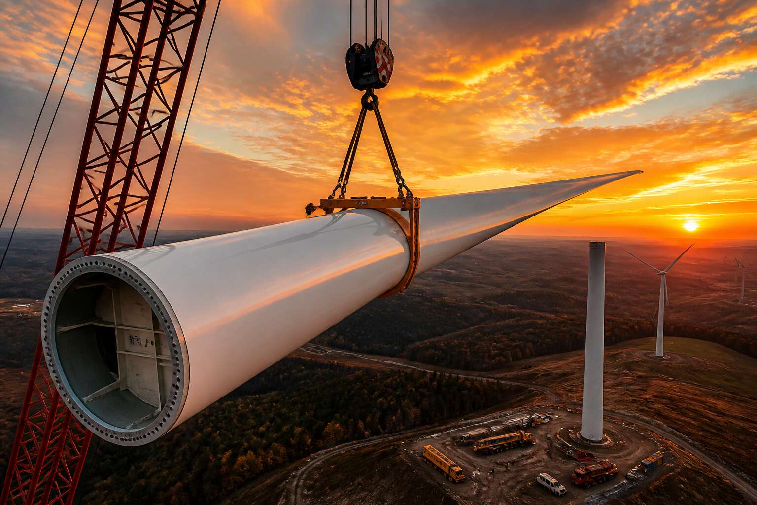
Anatomy and Materials of Turbine Wings
Core Structure and Root Design
At the junction where a wind turbine wing bolts to the rotor hub, the root bears forces that would fatigue ordinary steel! Modern blades rely on a pultruded carbon fiber spar cap running tip to root, while the core sandwich uses balsa wood or PET foam trapped between biaxial fiberglass skins. The layered anatomy is deceptively simple:
- Outer gelcoat for erosion protection
- Biaxial fiberglass skins for shear strength
- Balsa or PET foam core for buckling resistance
- Carbon fiber spar caps for bending loads
The root itself is a thick, circular laminate drilled for T-bolt connections. Loads concentrate here, so manufacturers taper the laminate toward the tip to shed mass. Some designs use a studded flange to transfer torque. A single wind turbine wing can exceed fifteen tonnes, yet its root laminate is only a few centimetres thick. That paradox drives every material choice.
Advanced Composite Materials
Every wind turbine wing demands a delicate balance between strength and weight. The shell uses layers of woven fiberglass and carbon fibre, each slice angled to handle specific strains. The carbon fibre spar cap carries bending loads, while the glass layers resist torsion. But modern blades depend on the resin that binds them, a thermoset epoxy that cures under vacuum to lock every fibre in place.
- Carbon fibre adds stiffness without weight
- Fiberglass offers damage tolerance
- Epoxy resins weather UV and moisture
Manufacturers also tweak the layup along the length, thickening the trailing edge near the root and refining it near the tip. The result is an aerofoil that twists under load, shedding energy rather than snapping. I have seen a wind turbine wing flex metres in a storm, and that flexibility comes from the composite layers working as one.
Blade Length and Weight Considerations
Longer blades capture more energy, but they also attract more load. A 100 metre blade weighs around 35 tonnes, and mass rises with the cube of length.
Blade length controls the swept area, which drives annual energy production. Weight dictates the hub, bearings, and tower foundation. These factors constrain each other. Manufacturers extend the wind turbine wing only when structural profiles can shed enough mass.
- Tip speed rises, increasing efficiency but also noise and erosion.
- Gravity loads oscillate with each rotation, straining the wing root.
- Stiffness drops relative to length, forcing predictable deformation.
The rotor diameter defines the entire turbine architecture. Every wind turbine wing is engineered to the exact kilogram and millimetre.
Aerodynamics and Performance Optimizations
Airfoil Shape and Lift Generation
The shape of a wind turbine wing dictates how efficiently it captures energy from moving air. Lift generation depends on the airfoil’s camber and angle of attack. As air accelerates over the curved suction side, pressure drops, creating a force that pulls the blade forward. This force, not the wind’s push, drives rotation. Modern airfoils use asymmetric profiles to optimize this effect across varying wind speeds.
Key aerodynamic factors include:
– Leading edge radius, which influences stall behavior
– Boundary layer control, which reduces drag
– Tip vortex management, which minimizes energy loss
Each element works together. A well-designed airfoil delays flow separation, allowing the wind turbine wing to maintain performance in turbulent South African wind regimes. The result is more consistent power output without increasing structural stress. Optimization is a balance between lift and drag, and small shape changes produce measurable gains over decades of operation.
Angle of Attack Adjustments
Every degree of pitch matters. A wind turbine wing operates in wind that shifts direction and speed constantly, especially in South African wind regimes. The angle of attack determines when the airfoil stalls. Too high, and lift collapses. Too low, and energy capture drops. Modern controllers adjust pitch in real time.
Consider these adjustments: rotate the blade to maintain optimal angle, respond to gusts, and shed load during extreme events. Sensors measure wind speed and direction, then command the pitch system.
- Fine tuning for steady winds
- Emergency feathering for storms
The result is a wind turbine wing that survives and produces power consistently. Dynamic tuning reduces fatigue on the structure without sacrificing output.
Surface Roughness and Impact on Efficiency
Dust storms and salty coastal air deposit stubborn residues on every wind turbine wing. We have watched these fine particles disturb the airfoil’s sensitive boundary layer across installations in the Karoo and the Western Cape. The blade may appear clean from a distance, yet measured energy losses from surface contamination alone fall in the 2% to 5% range.
Roughness sources include:
- Leading edge erosion from sand and dust storms
- Insect residue and rain droplet impact
- Salt spray corrosion in coastal installations
These surface defects trigger premature boundary layer transition. Laminar flow gives way to turbulence. Airfoil efficiency drops away. The pitch system reacts, but no controller can fix a rough surface!
Wake Effects and Turbine Spacing
A single wind turbine wing may perform beautifully, but place it behind another turbine and the story changes. Wake effects steal energy from downstream rotors. In South African wind farms, we measure output losses of 8% to 12% when spacing falls below five rotor diameters. The wake recovers slowly across the Karoo plateau, yet the turbulence lingers.
Turbine spacing demands a balancing act. Closer rows reduce land costs, but they increase fatigue loads on every blade. Proper layout requires modelling of wind rose, terrain roughness, and seasonal gusts.
Spacing considerations include:
– Rotor diameter multiples for row separation
– Offset staggering to diffuse wake cores
– Site-specific turbulence intensity data
Optimising this geometry lifts farm efficiency without adding material or blade length. That is the quiet gain in wind energy design!
Manufacturing Processes and Quality Control
Molding Techniques for Large-Scale Blades
Manufacturing a wind turbine wing demands precision rivaling aerospace engineering. Vacuum infusion molding uses differential pressure to draw resin through dry fiber, removing air pockets that weaken the structure. Mold temperature must stay within one degree of target; any deviation creates resin-rich zones.
We use segmented molds for the largest blades, and each section gets its own heating circuit! This allows local cure control, because a flawless exterior can hide internal voids. Our quality checks include:
- Ultrasonic scanning of every bonded seam.
- Dimensional measurement against the digital model.
- Core sampling from critical stress points.
These steps validate the entire structure. The outcome is a blade that performs predictably through years of coastal wind and highveld storms.
Automated Production Lines
Automation has removed the guesswork from wind turbine wing production. A decade ago, hand-layup ruled the factory floor, but manual processes create unpredictable cycle times. Our automated fibre placement heads lay material faster than any human hand, positioning every tow within half a millimetre of the digital twin.
When the wing leaves the mould, robotic cells handle trimming, drilling, and surface preparation. The line feeds live data to a central controller that adjusts parameters in real time. Critical inspections run without human intervention:
- Laser profilometry scans the entire surface for dimensional drift
- Shearography exposes subsurface disbonds before they become structural failures
- Automated ultrasonic mapping verifies every bond line across the root
These systems catch defects early, critical when one blade must weather coastal salt and Highveld hail. A wind turbine wing built this way meets tighter tolerances, wastes less material, and keeps delivery schedules intact under peak demand.
Non-Destructive Testing Methods
The most critical quality checks happen while the wind turbine wing is still on the line, not after it ships. Modern factories rely on non destructive testing methods that peer inside the laminate without damaging a single fibre. These techniques are the difference between a scheduled maintenance stop and a catastrophic field failure. It is far cheaper to find a defect in the plant than it is to send a crane truck to a remote Karoo ridge.
Standard visual inspections miss subsurface damage entirely. That is why quality departments lean on a suite of advanced tools:
– Ultrasonic testing maps bond lines at the root, verifying intimate contact between adhesive and structure.
– Shearography reveals internal disbonds by applying a subtle vacuum load and watching for surface anomalies.
– Laser profilometry scans the aerodynamic surface for any dimensional drift from the digital twin.
These methods feed directly into the manufacturing process. If the data shows a porosity spike, engineers adjust the infusion pressure on the next blade. For a wind turbine wing, consistency is not a luxury, it is a baseline requirement. Coastal salt spray and inland UV radiation will exploit any weakness over a 20 year service life. A robust NDT protocol keeps those vulnerabilities out of the sky.
Supply Chain and Logistics
A single wind turbine wing can travel 800 kilometres to the ridgeline. That trip exposes it to potholes, heat, and dust. So we build the wing to survive the journey.
Every batch of resin and glass fibre gets a fingerprint sample before infusion. We adjust cure cycles based on humidity readings from the factory floor. Quality control is a live process, not a final inspection.
The supply chain operates on strict windows. Each wind turbine wing leaves the plant with a handling certificate. Storage racks protect the aerodynamic surface from sagging. Delivery crews coordinate with wind forecasts to avoid sudden gusts.
Here is our shipment sequence:
1. Verify bond line integrity after demoulding.
2. Seal the root end against moisture.
3. Lock the blade into a shock absorbing cradle.
That last step matters most! A wing that arrives damaged costs more than the repair. It delays the whole installation schedule.
Sustainability in Production
A single wind turbine wing uses nearly 10 tonnes of composite material, and the waste from that process is a metric production teams sometimes overlook. We do not. Every offcut of glass fibre goes back into the supply chain as recycled filler. Resin drums are returned to the vendor for reprocessing. The factory floor runs on a closed-loop water system.
Sustainability in production means watching the numbers that do not appear on the spec sheet. Each month, our auditors run three checks:
- Resin consumption against batch weight.
- Fibre waste returned to the recycler.
- Energy use per blade against the baseline.
The same sensors that track curing temperatures also log energy draw, so the data arrives without extra admin. The result is a wind turbine wing with a documented environmental record. That transparency matters to buyers who answer to regulators, and to the communities that host the turbines.
Maintenance and Lifecycle Management
Inspection Schedules and Techniques
Inspection schedules for a wind turbine wing rarely follow a static calendar. I have seen operators extend intervals by 20 percent when SCADA data shows stable load patterns, while others tighten windows after lightning strikes. The technique matters just as much as timing.
Thermography catches subsurface delaminations that visual scans miss entirely. Ultrasonic testing maps internal crack growth along the spar cap with millimeter precision. Drone-based photogrammetry now makes leading edge erosion visible before it affects lift coefficients.
- Annual full structural surveys
- Quarterly edge inspections
- Post-storm targeted checks
Each method feeds a fatigue model, and that model dictates residual life estimates for every component on that wind turbine wing. Shortening an inspection cycle costs extra downtime, but skipping one risks catastrophic failure.
Leading Edge Erosion Protection
Erosion begins as a whisper, a faint roughness on the leading edge that grows louder with every gust of Karoo dust or coastal spray. For a wind turbine wing, this is the slow creep of inefficiency, a thief that steals lift and adds weight to maintenance ledgers. Protecting that edge is not merely about patching a surface, it is about defending the entire lifecycle of the asset against the relentless South African elements.
The choice of protection systems often comes down to the operating environment. A wind turbine wing facing the abrasive grit of the Northern Cape requires a heavier, more robust shield than one positioned in the milder inland breeze. Operators must evaluate the cost of a high-end polyurethane film against the potential revenue lost to reduced aerodynamic performance.
– Kit quality and adhesion properties
– Field application time versus factory curing
– Compatibility with existing repair putties
– Resistance to UV degradation and hail impact
These factors determine whether the protection is a temporary bandage or a long-term strategy. A lighter, flexible coating might suffice for lower wind speed sites, offering easier repair cycles. However, a high-energy coastal site demands a system that can withstand constant bombardment without cracking. The decision is a delicate balance between upfront capital and the long-term residual value of the wind turbine wing itself.
In South Africa, where grid stability is a constant conversation, every percentage of efficiency matters. A well-maintained leading edge keeps the blade profile true, helping the generator hit its rated output. This direct line between erosion protection and power production is what separates a proactive operator from a reactive one. The true cost of neglect is not the repair itself, but the months of degraded performance that precede it.
End-of-Life Recycling and Repurposing
Every wind turbine wing eventually reaches an inflection point where repair costs exceed residual value. Operators in South Africa face this decision amid rising material costs and tighter environmental regulations. The composite structure that delivered twenty years of service does not simply disappear at decommissioning. Glass fibre and epoxy resins require deliberate processing pathways, from mechanical shredding to cement kiln co-incineration. Some blade segments find second lives in civil infrastructure, as noise barriers or bridge elements. The choice between refurbishment and retirement shapes the lifecycle economics of the asset. A wind turbine wing carries embedded carbon that must be justified over its full operational span. Those who plan for end-of-life during procurement, rather than at the moment of failure, hold an advantage. Maintenance regimes that extend service life by even twelve months directly influence the residual value of every wind turbine wing in the fleet.
Innovations Shaping the Future
Smart Blades with Integrated Sensors
The modern wind turbine wing is no longer a silent slab of composite. It now streams continuous data through embedded fiber optic arrays and micro-electromechanical accelerometers. These sensors capture micro-strains and local vibrations, allowing operators to see stress patterns that were previously invisible.
This intelligence enables precise responses. For instance, when a blade detects abnormal turbulence, it can signal the nacelle to adjust yaw or pitch within milliseconds. Such feedback loops extend operational life and maximize energy capture.
- Strain gauges for fatigue tracking
- Thermal sensors for leading edge ice detection
- Vibration monitors for damage localization
Processing this data requires edge computing units mounted in the hub. They convert raw readings into actionable maintenance alerts, shifting the paradigm from schedule-based checks to condition-based insights. Every flex of the wind turbine wing becomes a whisper of its structural health.
Modular and Segmented Blade Concepts
Transporting a 100 meter wing is a logistical nightmare. Segmented blades offer an escape. By breaking the wind turbine wing into sections, manufacturers can move each piece on standard trucks and assemble them on site. This unlocks smaller roads and remote terrains across South Africa.
- Reduced transport costs
- Simplified repair access
- Tailored stiffness per segment
These modules demand new connection systems, like friction bolted joints or pre stressed couplers. I’ve seen prototypes that click together precisely enough to maintain aerodynamic continuity! The future wing may arrive in pieces but perform as a whole.
Biomimicry in Blade Design
A humpback whale flipper holds lift at angles 40 percent steeper than a smooth surface permits. The leading edge carries bumps called tubercles that delay flow separation. Engineers have transferred this geometry to a wind turbine wing. Lift holds longer, stall happens later, and pitch control demands less energy. Owl feathers show a second principle. Their serrated trailing edges break turbulence into micro vortices, reducing noise dramatically. This creates a blade quiet enough for residential areas. I have seen wind tunnel tests where the tubercle pattern shrinks flow separation by nearly a third. Three biological principles guide the work:
- Surface texture alters boundary layer adhesion.
- Edge geometry changes wake dynamics.
- Internal structural gradients distribute load without extra mass.
None of these are decorative. Each changes physical response at the surface or within the material. The future blade will combine these choices, informed by evolutionary evidence.
Active Control Strategies
The wind turbine wing now holds the potential to react faster than the gusts that strike it. Active control strategies are moving blades from passive profiles to responsive surfaces. Trailing edge flaps, embedded actuators, and continuous camber morphing allow the blade to shed load before the load arrives. Field tests show fatigue load reductions near 20 percent, and I expect that figure to climb.
These strategies group into three families:
- Micro actuation systems that bend the trailing edge in fractions of a second
- Flow control devices that energise the boundary layer on demand
- Structural damping that counteracts resonance in real time
Each family changes how the wind turbine wing interacts with turbulent air. The result is a blade that manages its own operational envelope. For South African sites with complex terrain, this responsiveness matters more than static efficiency.
Additive Manufacturing for Spare Components
One cracked trailing edge once meant a six week wait for a replacement. Additive manufacturing now prints that same wind turbine wing component in days. For South African operators, the distance to European suppliers becomes irrelevant when the spares are grown on site.
Laser sintering with glass reinforced nylon produces parts that match the stiffness of the original moulded sections. The material stack is predictable, and the fatigue behaviour is documented. What was a logistical bottleneck becomes a digital inventory. A hard drive holds the geometry, and a printer holds the material.
- Grippers and clamps for blade handling
- Internal ducting for dehumidification systems
- Replacement sensor housings for the wing surface
Additive manufacturing does not rely on exotic materials. It turns downtime into scheduled maintenance. The wind turbine wing remains the most expensive replaceable asset on a turbine, so making its spare parts available locally changes how farms manage their budgets.



0 Comments